
- Hardware type: Microcontrollers
- Connectivity: HTTP, MQTT, WIFI, Bluetooth
- Chip: ESP32
- Industry: Security
- Use cases: Smart energy, Environment Monitoring, Smart Office, Smart Retail, Smart Farming, Fleet Tracking, Health Care, Air Quality Monitoring, Waste Management, Tank Level Monitoring
- Platforms: Community Edition, Professional Edition, Cloud
- 概述
- 在ThingsBoard中创建设备
- 安装所需库和工具
- 连接设备到ThingsBoard
- 在ThingsBoard上查看数据
- 使用客户端和共享属性请求同步设备状态
- 使用共享属性控制设备
- 使用RPC控制设备
- 总结
概述
M5Stack Timer Camera F 是基于ESP32-D0WDQ6-V3的鱼眼摄像头模块,板载8 MB PSRAM与4 MB Flash。
OV3660传感器300万像素,DFOV 120°,最高分辨率2048×1536。
采用超低功耗设计,板载RTC(BM8563)可输出IRQ信号,用于睡眠与定时唤醒(睡眠电流低至2 µA)。
内置270 mAh电池,定时拍照(每小时一张)可续航超过一个月。
支持Wi-Fi图像传输与USB口调试,底部HY2.0-4P可扩展其他外设。
板载LED状态指示与复位键,便于程序开发与调试。
本指南将介绍如何在ThingsBoard上创建设备、
安装所需库与工具。
随后将修改代码并上传到设备,
并查看运行结果及通过导入的仪表板在ThingsBoard上查看数据。
设备将借助客户端与共享属性请求功能与ThingsBoard保持同步。
同时,我们将使用共享属性或 RPC 请求控制设备。
前置条件
继续本指南前,需具备:
在ThingsBoard中创建设备
为简化流程,我们将在界面中手动创建设备。
-
登录ThingsBoard实例并进入 实体 > 设备 页面。
-
点击右上角 ”+” 按钮并选择 添加新设备。
-
输入设备名称,例如 “My Device”。其他字段可保持默认,点击 添加 创建设备。
-
设备已添加完成。
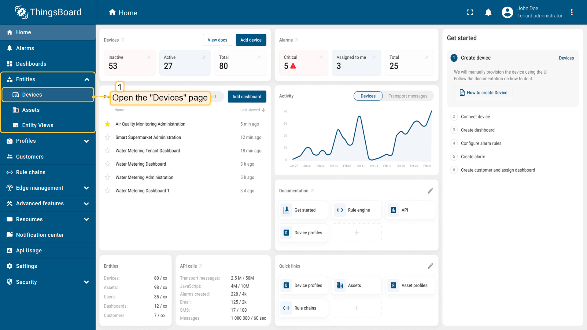
登录ThingsBoard实例并进入 实体 > 设备 页面。
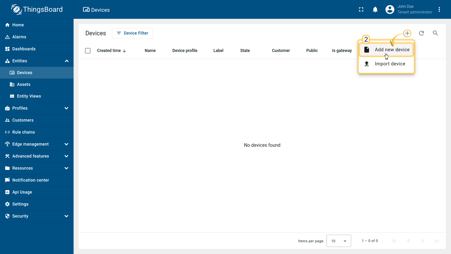
点击右上角 ”+” 按钮并选择 添加新设备。
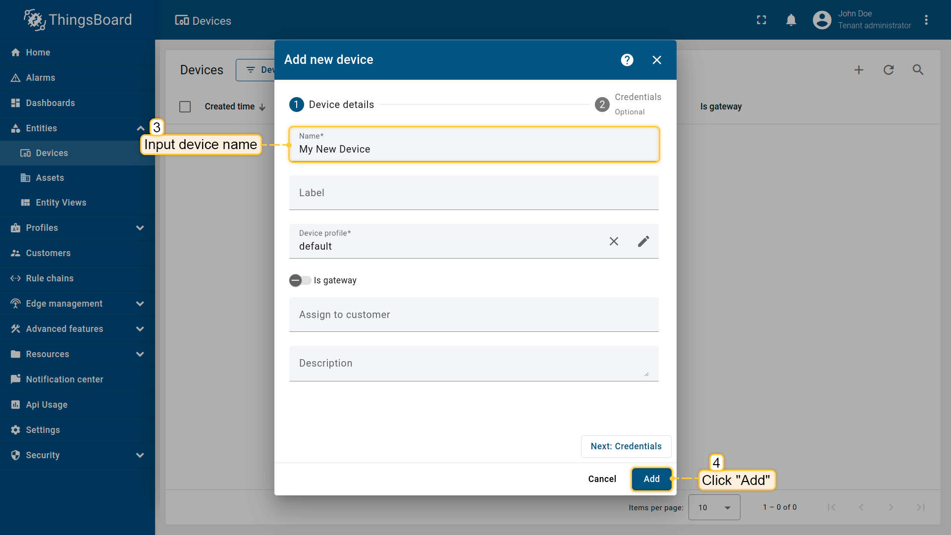
输入设备名称,例如 “My Device”。其他字段可保持默认,点击 添加 创建设备。
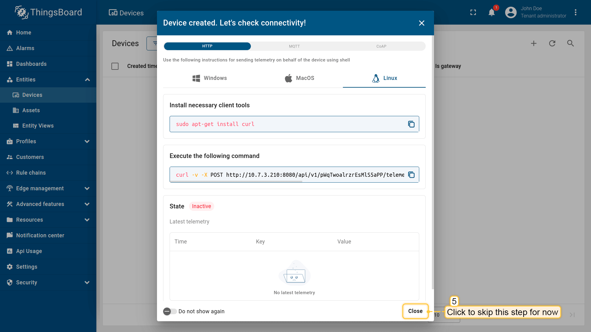
设备已添加完成。
安装所需库和工具
为Arduino IDE安装开发板:
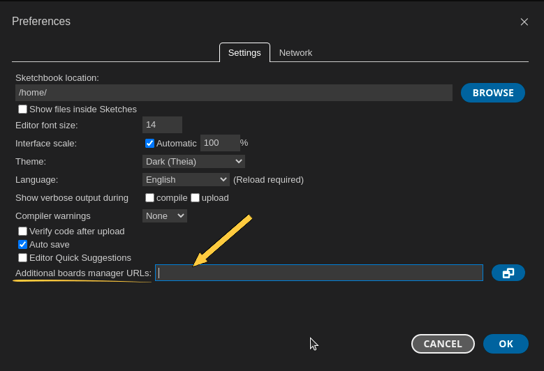
进入 文件 > 首选项,将以下URL添加到 附加开发板管理器网址 字段。
1
https://m5stack.oss-cn-shenzhen.aliyuncs.com/resource/arduino/package_m5stack_index.json
然后进入 工具 > 开发板 > 开发板管理器 并安装 M5Stack by M5Stack Official 开发板。
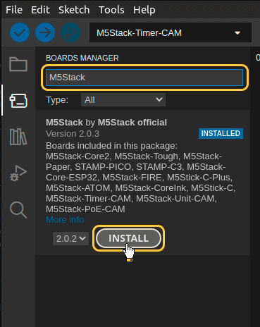
安装完成后,通过 工具 > 开发板 > M5Stack > M5TimerCAM (Or M5Stack-Timer-CAM in older ESP-IDF versions) 选择开发板。
用USB线连接设备与电脑,并在 工具 > 端口 > /dev/ttyUSB0 中选择设备端口。
端口随操作系统不同而不同:
- Linux下为 /dev/ttyUSBX
- MacOS下为 usb.serialX.. 或 usb.modemX..
- Windows下为 COMX。
安装ThingsBoard Arduino SDK需执行以下步骤:
-
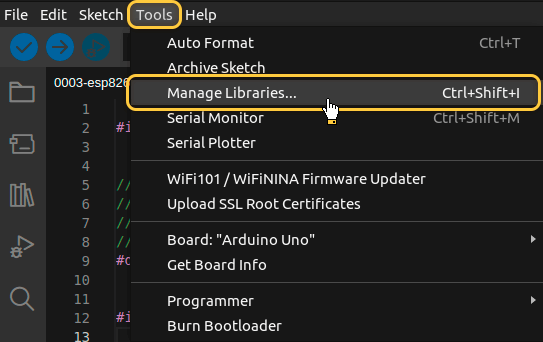
进入 工具 选项卡,点击 管理库。
-
在搜索框中输入 ThingsBoard 并点击找到的库的 安装 按钮。
进入 工具 选项卡,点击 管理库。
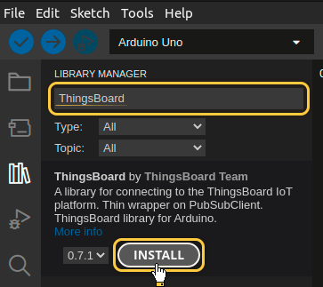
在搜索框中输入 ThingsBoard 并点击找到的库的 安装 按钮。
所有示例代码均需ThingsBoard库版本 0.14.0.
至此已安装全部所需库与工具。
连接设备到ThingsBoard
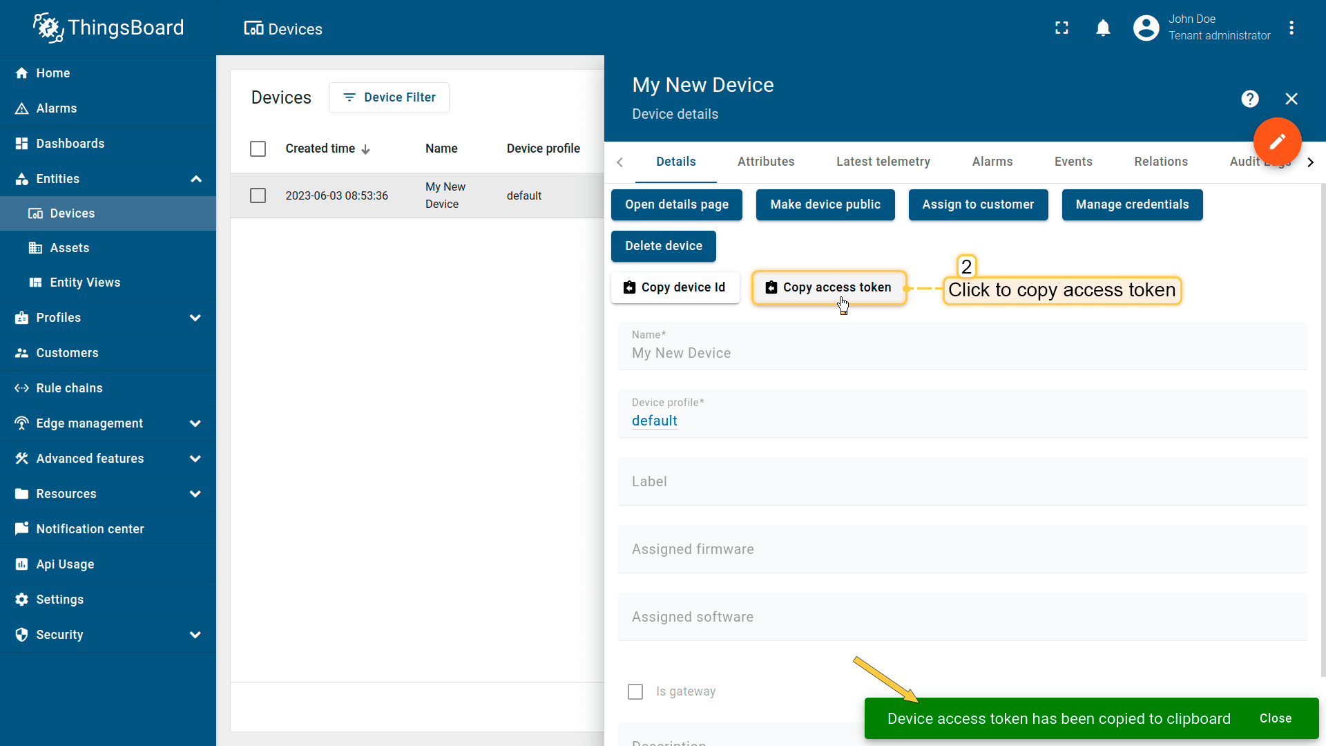
连接设备前,需先获取其凭证。
ThingsBoard 支持多种设备凭证类型,本指南使用默认自动生成的访问令牌(access token)。
-
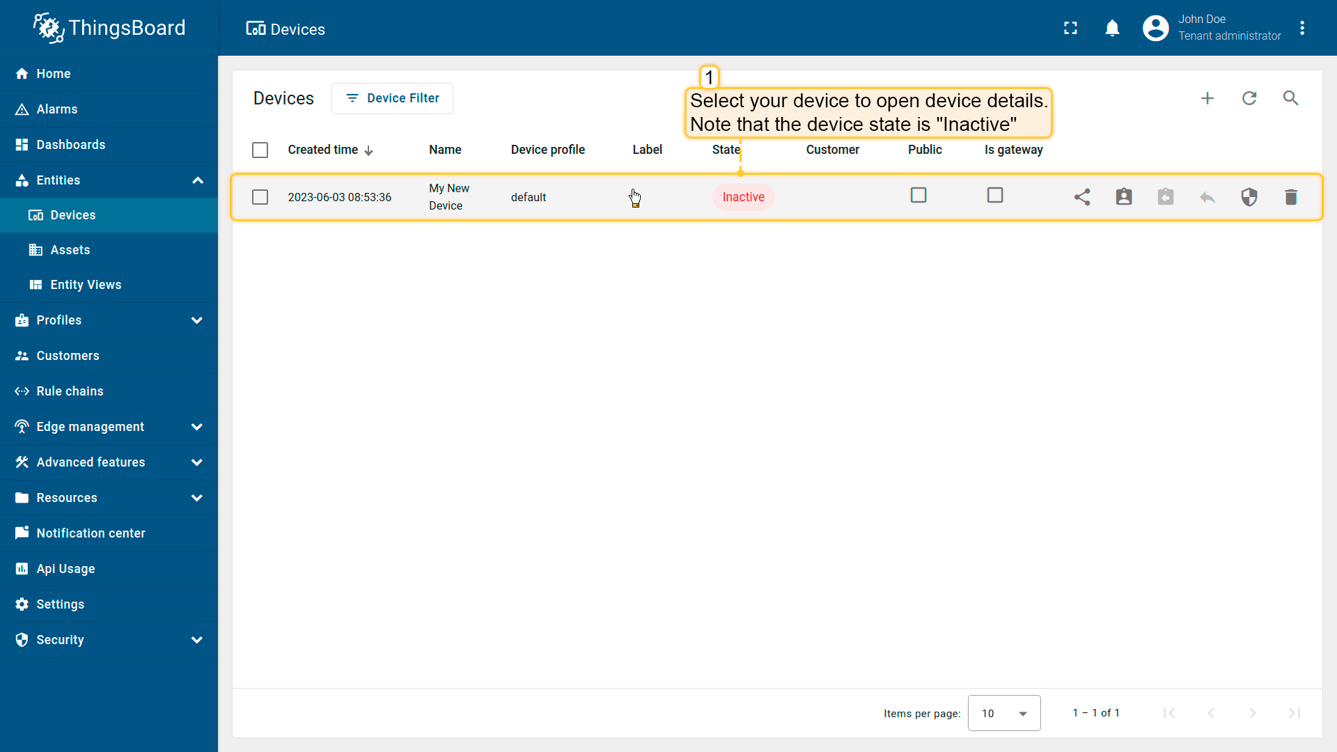
点击设备列表中的行以打开设备详情。
-
点击“复制访问令牌”。令牌将复制到剪贴板,请妥善保存。
点击设备列表中的行以打开设备详情。
点击“复制访问令牌”。令牌将复制到剪贴板,请妥善保存。
Now it’s time to program the board to connect to ThingsBoard.
To do this, you can use the code below. It contains all required functionality for this guide.
Data, send by this device may require increasing of the allowed message size for MQTT on your ThingsBoard instance.
To do this you can modify parameter NETTY_MAX_PAYLOAD_SIZE in thingsboard.yml file, default value on regular setup is 65535 bytes.
Required size depends on chosen resolution and quality.
Click to see dependency between resolution and approximate message size
| Framesize parameter value | Photo resolution | Approximate message size (in bytes) |
|---|---|---|
| FRAMESIZE_96X96 | 96x96 | 4608 |
| FRAMESIZE_QQVGA | 160x120 | 7200 |
| FRAMESIZE_QCIF | 176x144 | 9792 |
| FRAMESIZE_HQVGA | 240x176 | 12288 |
| FRAMESIZE_240X240 | 240x240 | 14400 |
| FRAMESIZE_QVGA | 320x240 | 19200 |
| FRAMESIZE_CIF | 400x296 | 29760 |
| FRAMESIZE_HVGA | 480x320 | 34560 |
| FRAMESIZE_VGA | 640x480 | 76800 |
| FRAMESIZE_SVGA | 800x600 | 144000 |
| FRAMESIZE_XGA | 1024x768 | 294912 |
| FRAMESIZE_HD | 1280x720 | 345600 |
| FRAMESIZE_SXGA | 1280x1024 | 491520 |
| FRAMESIZE_UXGA | 1600x1200 | 921600 |
| FRAMESIZE_FHD | 1920x1080 | 933120 |
| FRAMESIZE_P_HD | 720x1280 | 1036800 |
| FRAMESIZE_P_3MP | 864x1536 | 1776384 |
| FRAMESIZE_QXGA | 2048x1536 | 4718592 |
| FRAMESIZE_QHD | 2560x1440 | 5529600 |
| FRAMESIZE_WQXGA | 2560x1600 | 6144000 |
| FRAMESIZE_P_FHD | 1080x1920 | 6220800 |
| FRAMESIZE_QSXGA | 2560x1920 | 7864320 |
请勿忘记将占位符替换为您的真实Wi-Fi网络SSID、密码及ThingsBoard设备访问令牌。
连接所需变量:
| 变量名 | 默认值 | 说明 |
|---|---|---|
| WIFI_SSID | YOUR_WIFI_SSID | 您的Wi-Fi网络名称。 |
| WIFI_PASSWORD | YOUR_WIFI_PASSWORD | 您的Wi-Fi网络密码。 |
| TOKEN | YOUR_DEVICE_ACCESS_TOKEN | 设备访问令牌。获取方式参见 #connect-device-to-thingsboard |
| THINGSBOARD_SERVER | localhost | 您的ThingsBoard主机或IP地址。 |
| THINGSBOARD_PORT | 1883U | ThingsBoard服务MQTT端口。本指南可使用默认值。 |
| MAX_MESSAGE_SIZE | 100U*1024 | MQTT消息最大尺寸。应大于图片尺寸 + 约1024或更多。 |
| SERIAL_DEBUG_BAUD | 1883U | 串口波特率。本指南可使用默认值。 |
1
2
3
4
5
6
7
8
9
10
11
12
13
14
...

constexpr char WIFI_SSID[] = "YOUR_WIFI_SSID";
constexpr char WIFI_PASSWORD[] = "YOUR_WIFI_PASSWORD";

constexpr char TOKEN[] = "YOUR_ACCESS_TOKEN";

constexpr char THINGSBOARD_SERVER[] = "localhost";
constexpr uint16_t THINGSBOARD_PORT = 1883U;

constexpr uint32_t MAX_MESSAGE_SIZE = 100U * 1024;
constexpr uint32_t SERIAL_DEBUG_BAUD = 115200U;

...
Send data part (By default the example sends random value for temperature key and some WiFi information):
1
2
3
4
5
6
7
8
...
    tb.sendTelemetryData("temperature", random(10, 20));
    tb.sendAttributeData("rssi", WiFi.RSSI());
    tb.sendAttributeData("bssid", WiFi.BSSIDstr().c_str());
    tb.sendAttributeData("localIp", WiFi.localIP().toString().c_str());
    tb.sendAttributeData("ssid", WiFi.SSID().c_str());
    tb.sendAttributeData("channel", WiFi.channel());
...
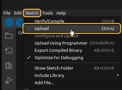
Then upload the code to the device by pressing Upload button or keyboard combination Ctrl+U.
在ThingsBoard上查看数据
ThingsBoard支持创建和自定义用于监控与管理数据、设备的交互式可视化(仪表板)。
通过ThingsBoard仪表板,您可以高效管理与监控IoT设备及数据。下面为我们的设备创建仪表板。
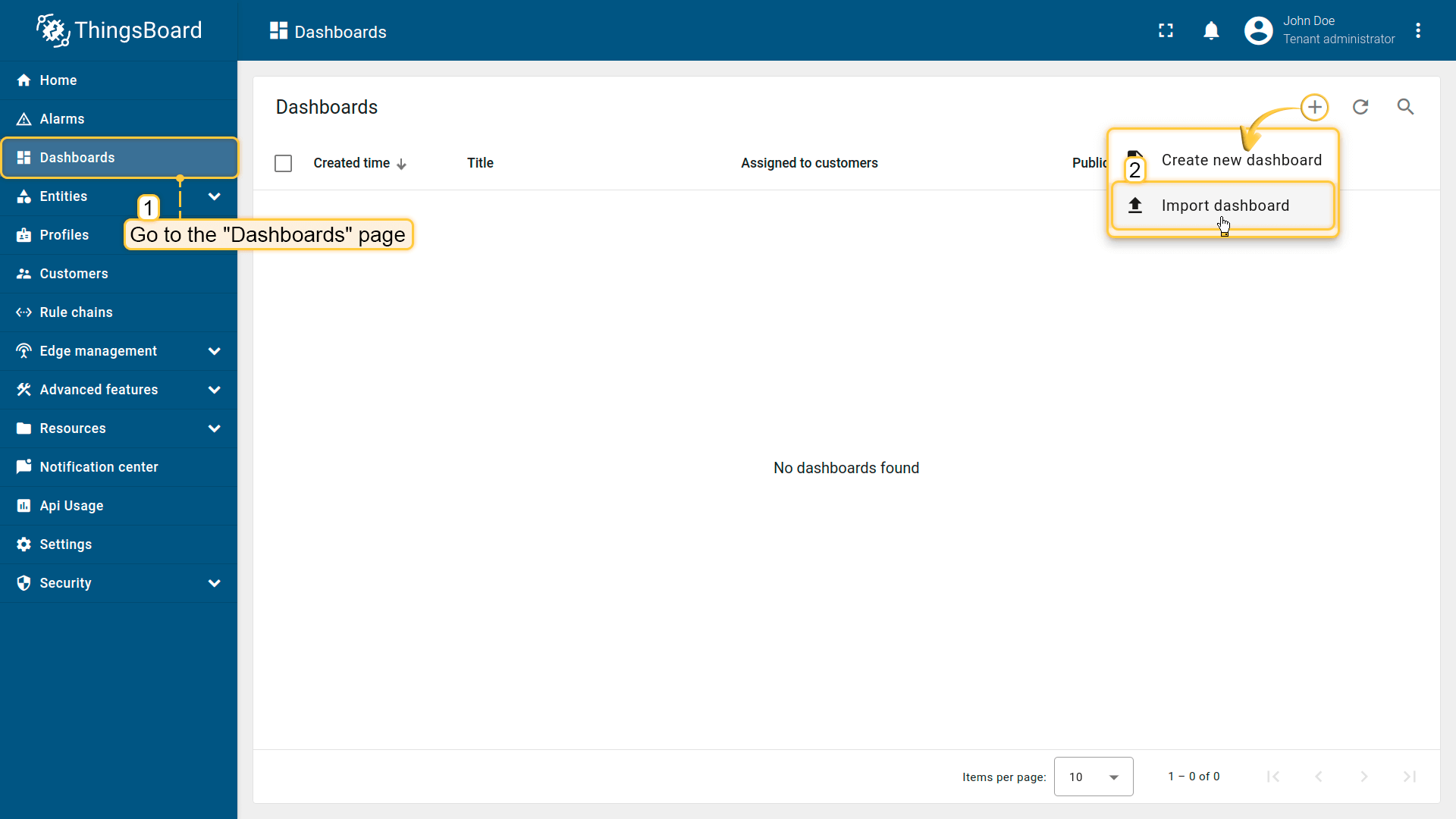
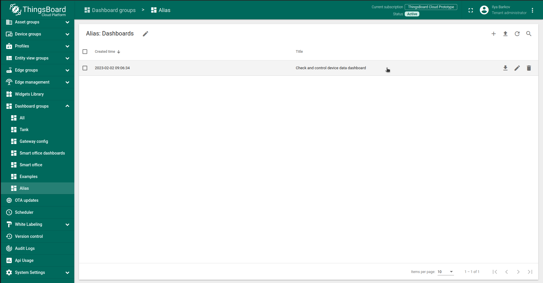
将仪表板添加到ThingsBoard需要导入。请按以下步骤操作:
- 首先下载 检查并控制设备数据仪表板 文件。
-
进入 仪表板 页面,点击右上角 + 按钮并选择 导入仪表板。
-
在仪表板导入窗口中上传JSON文件并点击 导入 按钮。
-
仪表板已导入。
进入 仪表板 页面,点击右上角 + 按钮并选择 导入仪表板。
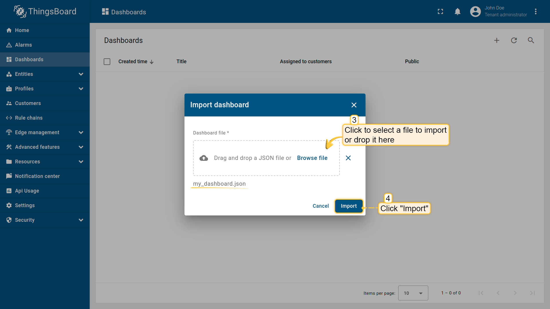
在仪表板导入窗口中上传JSON文件并点击 导入 按钮。
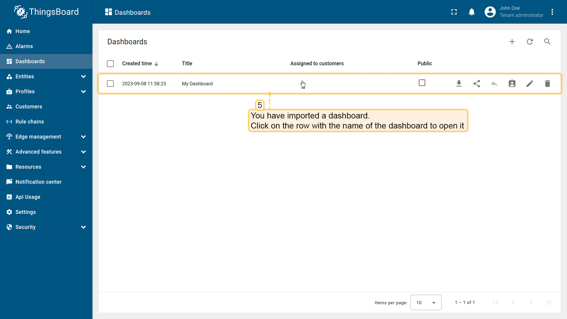
仪表板已导入。
检查并控制设备数据仪表板结构:
-
点击表格中的仪表板以打开导入的仪表板,查看设备数据。
-
检查数据和控制设备的仪表板视图。
-
从设备接收的属性。
-
ThingsBoard服务器上的设备信息。
-
查看LED模式变化历史的部件。
-
查看模拟温度历史的部件。
点击表格中的仪表板以打开导入的仪表板,查看设备数据。
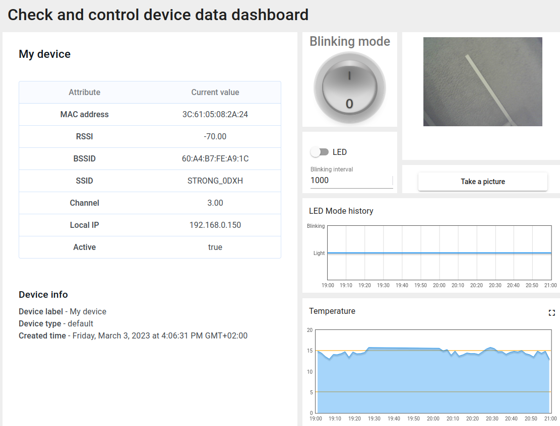
检查数据和控制设备的仪表板视图。
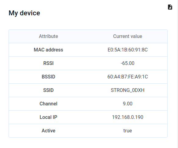
从设备接收的属性。
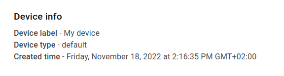
ThingsBoard服务器上的设备信息。
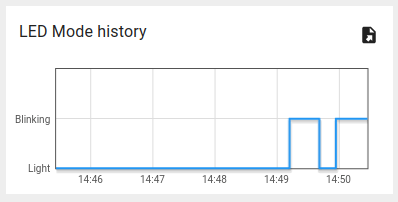
查看LED模式变化历史的部件。
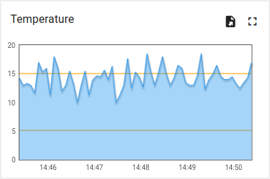
查看模拟温度历史的部件。
使用客户端和共享属性请求同步设备状态
为在启动时从ThingsBoard获取设备状态,代码中实现了相应功能。
以下为示例代码的相关部分:
- 引入模块以使用API功能:
1
2
3
4
5
6
7
8
9
10
11
...
#include <AttributeRequest.h>
...
Attribute_Request<2U, MAX_ATTRIBUTES> attr_request;
...
const std::array<IAPI_Implementation*, ...> apis = {
  ...
  &attr_request,
  ...
};
...
需在代码中定义要使用的API。
- 属性回调:
1
2
3
4
5
6
7
8
9
10
11
12
13
14
15
16
17
18
19
20
21
22
23
24
25
26
27
28
29
30
31
32
33
34
35
36
37
...
void processSharedAttributes(const JsonObjectConst &data) {
  for (auto it = data.begin(); it != data.end(); ++it) {
    if (strcmp(it->key().c_str(), BLINKING_INTERVAL_ATTR) == 0) {
      const uint16_t new_interval = it->value().as<uint16_t>();
      if (new_interval >= BLINKING_INTERVAL_MS_MIN && new_interval <= BLINKING_INTERVAL_MS_MAX) {
        blinkingInterval = new_interval;
        Serial.print("Updated blinking interval to: ");
        Serial.println(new_interval);
      }
    } else if(strcmp(it->key().c_str(), LED_STATE_ATTR) == 0) {
      ledState = it->value().as<bool>();
      digitalWrite(LED_BUILTIN, ledState ? HIGH : LOW);
      Serial.print("Updated state to: ");
      Serial.println(ledState);
    }
  }
  attributesChanged = true;
}

void processClientAttributes(const JsonObjectConst &data) {
  for (auto it = data.begin(); it != data.end(); ++it) {
    if (strcmp(it->key().c_str(), LED_MODE_ATTR) == 0) {
      const uint16_t new_mode = it->value().as<uint16_t>();
      ledMode = new_mode;
    }
  }
}
...
// Attribute request did not receive a response in the expected amount of microseconds
void requestTimedOut() {
  Serial.printf("Attribute request timed out did not receive a response in (%llu) microseconds. Ensure client is connected to the MQTT broker and that the keys actually exist on the target device\n", REQUEST_TIMEOUT_MICROSECONDS);
}
...
const Attribute_Request_Callback<MAX_ATTRIBUTES> attribute_shared_request_callback(&processSharedAttributes, REQUEST_TIMEOUT_MICROSECONDS, &requestTimedOut, SHARED_ATTRIBUTES_LIST);
const Attribute_Request_Callback<MAX_ATTRIBUTES> attribute_client_request_callback(&processClientAttributes, REQUEST_TIMEOUT_MICROSECONDS, &requestTimedOut, CLIENT_ATTRIBUTES_LIST);
...
共有三个回调:
- 共享属性回调:专用于共享属性,主要接收包含闪烁间隔的响应,以确定合适的闪烁周期;
- 客户端属性回调:专用于客户端属性,接收LED模式与状态信息,收到后保存并应用这些参数;
- 请求超时回调:在属性数据请求超时时触发,用于处理超时。
此功能使设备在重启后能保持实际状态。
- 属性请求:
1
2
3
4
5
6
7
8
9
10
11
12
13
...
  // Request current states of shared attributes
  if (!attr_request.Shared_Attributes_Request(attribute_shared_request_callback)) {
    Serial.println("Failed to request for shared attributes");
    return;
  }

  // Request current states of client attributes
  if (!attr_request.Client_Attributes_Request(attribute_client_request_callback)) {
    Serial.println("Failed to request for client attributes");
    return;
  }
...
为使回调能接收数据,需向ThingsBoard发送请求。
使用共享属性控制设备
还可通过共享属性更新功能修改闪烁周期。
-
修改闪烁周期只需在仪表板上更改数值即可。
-
按勾选图标应用后,将显示确认消息。
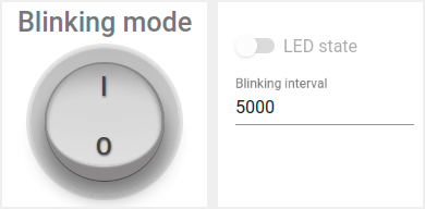
修改闪烁周期只需在仪表板上更改数值即可。
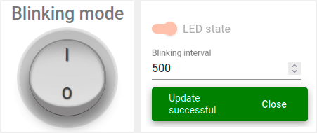
按勾选图标应用后,将显示确认消息。
在关闭闪烁时改变状态,可使用同一部件中的开关:
-
仅当关闭闪烁模式时方可操作。
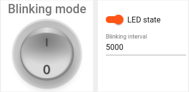
仅当关闭闪烁模式时方可操作。
实现该功能使用变量 “blinkingInterval”,出现在以下代码中:
- Connecting modules to use API functionality:
1
2
3
4
5
6
7
8
9
10
11
...
#include <AttributeRequest.h>
...
Attribute_Request<2U, MAX_ATTRIBUTES> attr_request;
...
const std::array<IAPI_Implementation*, ...> apis = {
  ...
  &shared_update
  ...
};
...
使用属性请求功能需引入相关模块并将其作为所用API的一部分。
- 共享属性更新回调:
1
2
3
4
5
6
7
8
9
10
11
12
13
14
15
16
17
18
19
20
21
22
23
24
25
26
27
28
29
...

void processSharedAttributes(const JsonObjectConst &data) {
  for (auto it = data.begin(); it != data.end(); ++it) {
    if (strcmp(it->key().c_str(), BLINKING_INTERVAL_ATTR) == 0) {
      const uint16_t new_interval = it->value().as<uint16_t>();
      if (new_interval >= BLINKING_INTERVAL_MS_MIN && new_interval <= BLINKING_INTERVAL_MS_MAX) {
        blinkingInterval = new_interval;
        Serial.print("Updated blinking interval to: ");
        Serial.println(new_interval);
      }
    } else if(strcmp(it->key().c_str(), LED_STATE_ATTR) == 0) {
      ledState = it->value().as<bool>();
      digitalWrite(LED_BUILTIN, ledState ? HIGH : LOW);
      Serial.print("Updated state to: ");
      Serial.println(ledState);
    }
  }
  attributesChanged = true;
}

...
// Attribute request did not receive a response in the expected amount of microseconds
void requestTimedOut() {
  Serial.printf("Attribute request timed out did not receive a response in (%llu) microseconds. Ensure client is connected to the MQTT broker and that the keys actually exist on the target device\n", REQUEST_TIMEOUT_MICROSECONDS);
}
...
const Attribute_Request_Callback<MAX_ATTRIBUTES> attribute_shared_request_callback(&processSharedAttributes, REQUEST_TIMEOUT_MICROSECONDS, &requestTimedOut, SHARED_ATTRIBUTES_LIST);
...
- 订阅共享属性更新:
1
2
3
4
5
6
...
    if (!shared_update.Shared_Attributes_Request(attribute_shared_request_callback)) {
      Serial.println("Failed to request for shared attributes");
      return;
    }
...
- 闪烁相关代码:
1
2
3
4
5
6
7
8
9
10
11
12
13
14
...

  if (ledMode == 1 && millis() - previousStateChange > blinkingInterval) {
    previousStateChange = millis();
    ledState = !ledState;
    digitalWrite(LED_BUILTIN, ledState);
    tb.sendTelemetryData(LED_STATE_ATTR, ledState);
    tb.sendAttributeData(LED_STATE_ATTR, ledState);
    if (LED_BUILTIN == 99) {
      Serial.print("LED state changed to: ");
      Serial.println(ledState);
    }
  }
...
可修改逻辑以实现目标,并添加自定义属性处理。
使用RPC控制设备
可手动切换LED状态,并在常亮与闪烁模式间切换。 可使用仪表板中的以下部分:
-
使用开关部件将LED设为常亮。
-
使用圆形开关部件将LED设为闪烁模式。
使用开关部件将LED设为常亮。
使用圆形开关部件将LED设为闪烁模式。
注意:仅在关闭闪烁模式时可更改LED状态。
示例代码中实现了 RPC 命令 处理。
实现设备控制使用了以下代码部分:
- Connecting modules to use API functionality:
1
2
3
4
5
6
7
8
9
10
11
12
...
#include <Server_Side_RPC.h>
...
Server_Side_RPC<..., ...> rpc;
...

const std::array<IAPI_Implementation*, ...> apis = {
    ...
    &rpc,
    ...
    }
...
使用RPC需引入相关模块并将其作为所用API的一部分。
- RPC请求回调:
1
2
3
4
5
6
7
8
9
10
11
12
13
14
15
16
17
18
19
20
21
22
23
24
25
26
27
28
29
30
31
32
33
34
35
36
...

void processSetLedMode(const JsonVariantConst &data, JsonDocument &response) {
  Serial.println("Received the set led state RPC method");

  // Process data
  int new_mode = data;

  Serial.print("Mode to change: ");
  Serial.println(new_mode);
  StaticJsonDocument<1> response_doc;

  if (new_mode != 0 && new_mode != 1) {
    response_doc["error"] = "Unknown mode!";
    response.set(response_doc);
    return;
  }

  ledMode = new_mode;

  attributesChanged = true;


  response_doc["newMode"] = (int)ledMode;
  // Returning current mode
  response.set(response_doc);
}

...

const std::array<RPC_Callback, 2U> callbacks = {
  RPC_Callback{ "setLedMode", processSetLedMode },
  RPC_Callback{ "takePicture", processTakePicture }
};

...
- 订阅RPC请求:
1
2
3
4
5
6
...
    if (!rpc.RPC_Subscribe(callbacks.cbegin(), callbacks.cend())) {
      Serial.println("Failed to subscribe for RPC");
      return;
    }
...
开发板集成摄像头后,可拍照并在仪表板上查看。
-
可通过按下ThingsBoard仪表板上的按钮从摄像头模块拍照。
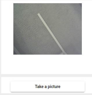
可通过按下ThingsBoard仪表板上的按钮从摄像头模块拍照。
通过向设备发送 “takePicture” RPC实现拍照。
以下代码用于拍照。
1
2
3
4
5
6
7
8
9
10
11
12
13
...

bool captureImage() {
  camera_fb_t *fb = NULL;
  fb = esp_camera_fb_get();
  if (!fb) {
    return false;
  }
  encode((uint8_t *)fb->buf, fb->len);
  esp_camera_fb_return(fb);
  return true;
}
...
JSON无法直接传递照片原始字节数组,故需将字节编码为Base64:
1
2
3
4
5
6
7
8
9
...
void encode(const uint8_t *data, size_t length) {
  size_t size = base64_encode_expected_len(length) + 1;
  base64_encodestate _state;
  base64_init_encodestate(&_state);
  int len = base64_encode_block((char *)&data[0], length, &imageBuffer[0], &_state);
  len = base64_encode_blockend((imageBuffer + len), &_state);
}
...
编码后的图片在主循环中发送:
1
2
3
4
5
6
...
if (sendPicture) {
tb.sendTelemetryData(PICTURE_ATTR, imageBuffer);
sendPicture = false;
}
...
可修改代码以实现您的目标,并添加自定义RPC命令处理。
总结
现在您可以轻松将M5Stack Timer Camera F连接到ThingsBoard并开始发送数据。
进一步了解可查阅ThingsBoard文档, 学习创建仪表板可视化遥测、 配置告警规则实时监控设备行为等核心功能。